![]()
![]()
![]()
![]()
![]()
![]()
![]()
----------
![]()
|
Curio's - The "Practical Research" File, of Mike Skeet - Paper No.6 |
|
|
|
THE MID & SIDE MIC TECHNIQUE |
|
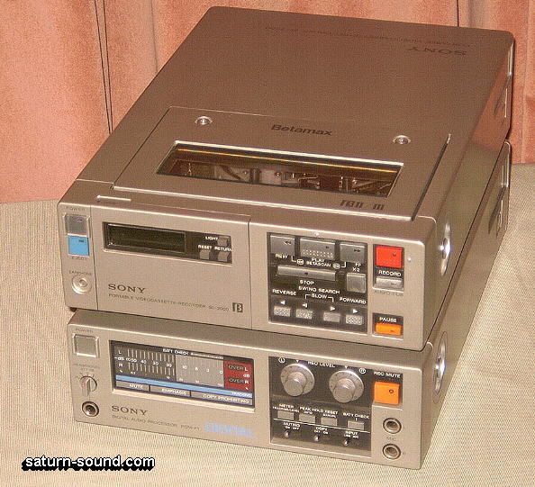
In the writer’s early use of Mk3 and Mk4 SoundField Microphones, and their control unit’s stereo outputs, fed straight into the line inputs of a Sony F1 (Pic. One), for 16 Bit / 44.1 Khz digital recordings on Beta video tapes, you got used to the variable polar patterns and the adjustable stereo width.
From memory, it didn’t seem immediately obvious that Mid & Side processing was involved, but when you read about the facilities of M&S with other mics, it seemed that it must be true, and opened the door to trying the technique with many other combinations of other maker’s microphones.
The Mid mic can be of any polar pattern, the Side mic has to be a figure of eight. The latter is arranged vertically coincident ‘side ways’ facing, compared to the forward facing Mid mic, which is used pointing at the centre of the soundstage being recorded.
Initially the writer used an STC (now Coles) 4038 ribbon, with a JVC electret cardioid for the Mid. Other Mid mics were then used, such as the Sennheiser MKH40 cardioid. That led to it being used with its sibling figure of eight, the MKH30, in a smaller set-up. Following that, the MKH30 became associated with a DPA4060 omni, with or without an ‘Acoustic Ball’ attached.
Further on, the Sennheiser variable polar pattern MKH80 became a favourite as the Mid, then the MKH800 Twin for polar pattern choice on the mixer, instead of having to go out in front of the audience, if one was that keen to change it!
The Pearl DS60 four rectangular cardioid capsule mic, allows a variable polar pattern Mid choice, with its forward and rear facing capsules. Its two side facing capsules are used as a figure of eight. There has always been a ‘ribbon mic’ characteristic to the sound from the DS60, as the rectangular diaphragms have ‘spread’ resonances.
Of course, Schoeps mics had to be used and their CCM8 figure of eight was associated with a CCM4 cardioid, and then a CCM21, and now the present very neat rig, is the new wide cardioid CCM22 along with the CCM8.
M&S USER ATTRIBUTES
The centre soundstage being captured is directly covered by the fact that Mid mic is directly pointing at that centre soundstage. The stereo moves out symmetrically to the left and right, with the variable width available, via the faders.
There is an inherent mono compatibility compared to any spaced out pair of mics. The ORTF 17cm spaced pair of cardioids angled at 110 degrees, do produce some good stereo recordings – the ‘ear spacing’ of the mics undoubtedly makes this possible, compared to the ‘dull’ stereo produced by using the same two mics, vertically coincident and angled at 90 degrees!
However, the centre of the soundstage is ‘off axis’, as far as both of the mics are concerned, especially at higher frequencies, due to fact that most mics are more directional at higher frequencies.
M&S DECODING
The correct way to align the M&S pair is to get the Side mic vertically coincident with the forward facing Mid. The inherent aspect of a figure of eight polar pattern is that the sound from the right is 180 degrees out of phase with the sound coming from the left, hence the very high degree of rejection of sound coming directly from between the two lobes of its polar pattern.
The Mid mic signal is fed in phase, to both the left and right stereo. The Side mic signal is fed to the stereo left, in phase with the Mid mic feed. With its phase inverted signal, it is also fed to the stereo right. This ensures that left to right stereo relates to what you would judged from behind the mics.
In simple mathematical terms, Left = M+S and the Right = M-S. You can also think of the Mid signal being the Sum of the left and the right, and the Side signal being the Difference between the left and right. The side mics channel’s phase switch can be used to invert the left/right stereo, like when slinging the rig, and you are using it upside down for convenience.
Few mic pre-amps and not all mixers have M&S decoding facilities, although on some mixers you can ‘contrive’ the decoding with the use of just three channels. With a ‘proper’ M&S decoding facility, it should take place after the mic amps, their phase switches, gain controls, and any insert jack sockets. Two channel faders will be used for the decoded Mid and Side signals, one for Mid mic level and the second for Side mic level, which gives you the variable width.
Both panpots will be set to centre, however there can be a use of the Mid mic’s panpot, to subtly correct the position of a particular centre image, should a soloist being slightly off centre. Curiously after 30 years, the writer has now discovered that it is a good idea to have some ‘trim’ pots, after the M&S decoding, to vary the left and right levels by a few dBs, to allow adjustment of the overall stereo placement, like you can easily do with ordinary stereo pairs!
IN CONCLUSION
M&S decoding with two figure of eight mics, produces two figure of eights, but with a variable width and, of course, with one of them physically pointing to the soundstage centre, from the outset. An omni mid mic results in two cardioids at 180 degrees, but never the less with the likely HF forward directionally of the mid omni, possibly being an asset?
If a cardioid is used as a mid mic, you end up with two hypercardioid patterns, with variable width. In the writer’s early use of the SoundField mic, it often ‘sounded right’ with its pattern switch position showing Hypercardioid! Hence one now usually carries on with cardioids as the M&S mid mic.
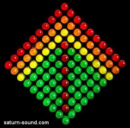
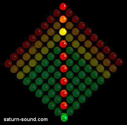
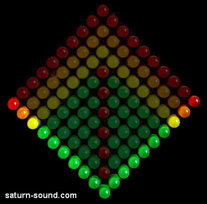
An asset in any stereo recording is to have is something like the Frank Fox invention ‘The Box’, which has 100 LEDs (Pic. Two) responding to the relationship of the ‘In Phase and Out of Phase’ content within the left and right stereo signals. With decoded M&S signals, the Mid mic on its own shows as a centre vertical line (Pic. Three), the Side mic on its own shows a Vee at the edges of the display (Pic. Four). Any excess width is visually revealed with the resulting stereo display showing an emphasis of the Vee contribution. For further information about "The Box" www.tabor-audio.co.uk
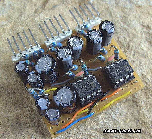
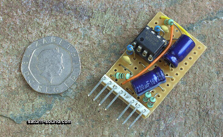
The writer uses Virtual Earth circuits with 5532 ICs for the M&S decoding in the various DIY mic-pres / mixers constructed over the many years. The Mic amps initially made use of Analogue Devices SSM2017 ICs, now SSM2019 (Pic. Five). A stepped gain range of 60dB is available. The powering needs 15-0-15 DC, for the SSM mic amps, and 48V DC for the Phantom Powering. It is easy to make use of strip Veroboard as plug in units (Pic. Six), which allows more compact sizes of aluminium cases for the overall DIY construction.
Up-dated 15/05/11 |
|
|