----------
|
Curio's - What about the AKG C24 ? |
|
|
The AKG C24 |

|
|
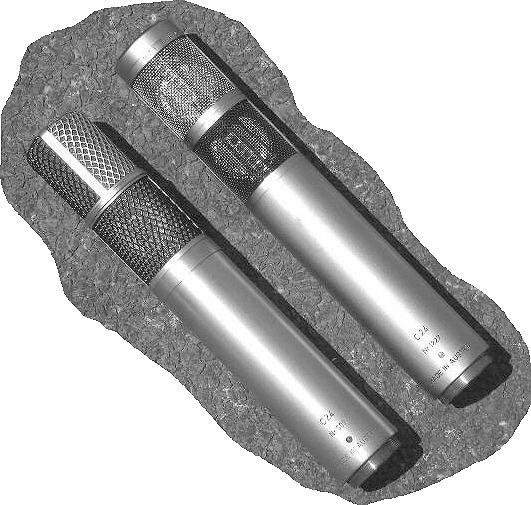
The AKG C24 "Stereo" microphone, being purpose designed and manufactured for "Stereo" recording. |
|
|
Of course, the C24 can also be used as two completely independent "Mono" type microphones, alas in very close proximity. |
|
|
There are two versions of the C24 i.e. Mk1, with it's "Pressed Brass" Diamond pattern mesh grills and the MK2 with Brass "Wire-mesh" grills. There are also very minor differences to the circuit's. These being associated with the polarizing voltage's applied to the capsules and a few component value changes. |
|
|
Both of the electronic channels, on separate PCB's, being enclosed in one common case. With the 1" diameter capsules, being mounted as close, as physically possible, to one another. |
|
|
The two "Independant" capsules/channels can easily be arranged to work as a "Crossed pair" (AB) or in "Middle and Side" (MS) technique. |
|
|
Mk1 and Mk2 versions of the AKG C24 "Stereo" microphone. |
|
| C24 = 2 x C12 ? | |
|
I am very often asked, "Isn't the C24 just the same as two C12's in a single housing ?". |
|
|
So many people seem to think that it is the situation. In 1962, even the dear old BBC appeared to think so. See their "Programme Operations Training Manual". |
|
|
Well, |
|
|
I am sorry to disappoint ..... but I am afraid to say that is not the situation. |
|
| Why ? | |
| First of all, let us see what the C12 and the C24 have in common. | |
| 1 - They are both based around the "Original" CK12 type capsules | |
| 2 - They are both based around the 6072 (12AY7), double triode, valve. | |
| 3 - They are both based around the AKG T14/1 "Impedance" matching, output transformer's. | |
| Note - "Early" examples of the AKG C12 microphone, used a larger output transformer, type V2148 | |
|
However, the similarity between the C12 and the C24 ends there. Both in electrical design and sound quality. |
|
| The difference's ! | |
|
If we take a look at the circuitry of the C24 i.e. Just one channel, and compare it to the C12, then all becomes blatantly clearer. |
|
| 1 - Grid Biasing Arrangement | |
|
The "Grid" biasing arrangement is quite different in both microphones i.e. The C12 uses a "Specific" feed from the associated N12 power supply unit, for "Grid Bias", whereas the C24 is "Self Biasing", through the use of a 200M ohm "Grid" resistor and a 27k ohm "Cathode" resistor, together with the associated 33uF "Cathode" decoupling capacitor. |
|
|
These differences having a very noticeable effect on the "Slope" of the valve, and therefore it's "Transfer" characteristics. Also effecting the "Low End" response/characteristic of the microphone. |
|
| 2 - Output Coupling Capacitor Value | |
|
The output coupling capacitor, to the matching transformer, is of a different value i.e. A 0.5uF capacitor is used in the C12, as opposed to a 1uF capacitor in the C24. |
|
|
Thus changing the "Low End" response, by a "Whole Octave" at the -3dB point i.e. There is greater "Bass Extension" on the C24, compared to that of the C12. |
|
| 3 - Valve Anode Decoupling | |
| The valve anode, of the C24, is decoupled to earth via a 100pF capacitor. | |
|
Thus changing the quality of the extreme "Top End" and "Transient" response of the microphone. |
|
|
Note - To accommodate the "Grid Biasing" arrangement, there are also differences between the associated N12 PSU, for the C12, compared to the N24 PSU, for the C24. |
|
| Summary, ..... my own thoughts ! | |
|
The design of C12, is based around the principles used during the middle of the 1950's. Especially with respect to the "Grid Biasing" technique utilized in the C12's electronics'. Therefore, this is probably the main reason for the C12's "Magical" quality, and that "Particular Sound" which is so often associated with units of that period and design technique i.e. Full and clean, but soft and spacious. |
|
|
The C24, being of a latter design and therefore using different design principles, takes on a sound that one associates with "Self Biased" valve equipment. Being somewhat "Dryer" and appearing somewhat "Harder" than one expects from valve equipment. |
|
|
|
|