![]()
![]()
![]()
![]()
![]()
![]()
![]()
----------
![]()
|
Valve Microphones - VM-212, Design and Construction |
|
|
I was approached by Martin Turner (Wishbone Ash), and asked if I had a secondhand AKG C12 for sale. At the time, I did not. I explained the scarcity of such microphones, together with the price tag that was being asked for them. |
|
|
The AKG C12VR was considered as an alternative, but rejected on the basis of the microphone sounding somewhat different to an original AKG C12. Basically this was due to design differences i.e. The AKG C12VR uses a totally different circuit design, to the original AKG C12. Both for the microphone and, "Importantly" in the case of the AKG C12, the power supply. |
|
|
I considered the idea of building a "Custom" model, based around my "Missing Link" VM-951 design. Modifying the appropriate parts/design as required. Used together with the associated "Missing Link" VP-120/6-RV "Replacement" power supply, I could offer a microphone, that would meet my clients requirements. The microphone design would use very slightly different value components to that of the original AKG C12, to stay clear of any copyright problems. The main difference, being the use of a "Larger" out-put matching transformer (See later). This would offer greater "Headroom", especially at LF, whilst still retaining that AKG C12 sound. |
|
|
After careful consideration by my client, the go-ahead to build, was given ....this was back in 2002. |
|
|
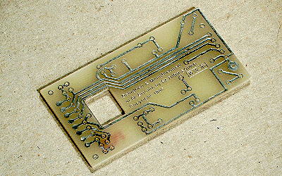
The electronics of the VM-212 is built on the "Standard" VM series PCB, part M10-01, designed back in 1996. The design allows for variations in impedance converter/pre-amp formats, to be incorporated onto the same "Standard" PCB. Thus catering for the design difference's between the VM-951 and the VM-212. A few "Designated" cuts are required on some of the PCB tracks. The capsule coupling capacitor, is wired directly between the capsule and the grid of the valve. Keeping stray capacitance down to a minimum and therefore, helping to maintain audio clarity and transit response. |
|
| PCB type M10-01 | |
|
The internal assembly, including the base and connector of the microphone, is coupled together via strong, yet not brittle, ABS type moldings. The lower molding, shown on the left in the picture, holds the custom "Sowter" out-put matching transformer in place against the base of the microphone. Also being the lower half of the PCB mount. The upper molding, shown on the right in the picture, carries the capsule and valve socket. Also being the upper half of the PCB mount. This arrangement, is the same as that employed in the VM-951 microphone. |
|
| Output transformer and capsule mount ABS moldings | |
|
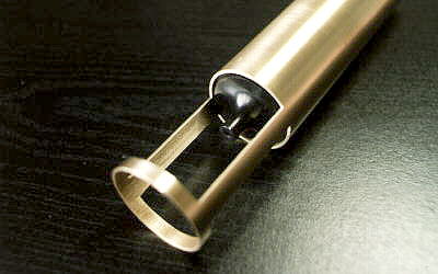
The housing tube, of the VM-212, is the same as that used on the VM-951. Machined "On-site" from a single piece of medium gauge Brass tube. Thus making the microphone solid, without being unduly "Heavy". The most difficult area to machine, being the two "Cut-outs" for the mesh. Apart from the electrical screening properties of brass, the material was also chosen for it's suitability of being electro-plated or powder paint coated, during later stages in manufacture. |
|
| "Cut-outs" for the mesh, in top of housing tube | |
|
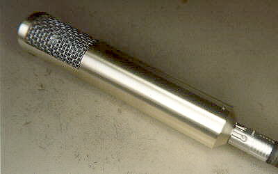
The finished casework of the very first VM-212, is shown complete with mesh and cable connector, less electronics, and is now ready for the powder paint coating. One of the many important aspects to consider, is to insure that the mesh makes good electrical contact with the housing tube i.e. earth/screen of the microphone. Failure to do so will cause future problems with hum etc. To help guarantee a "Long Term" solution to this problem, the mesh is earthed via two "Different" methods, alas without creating any earth loops. |
|
| Ready for the powder paint coating | |
|
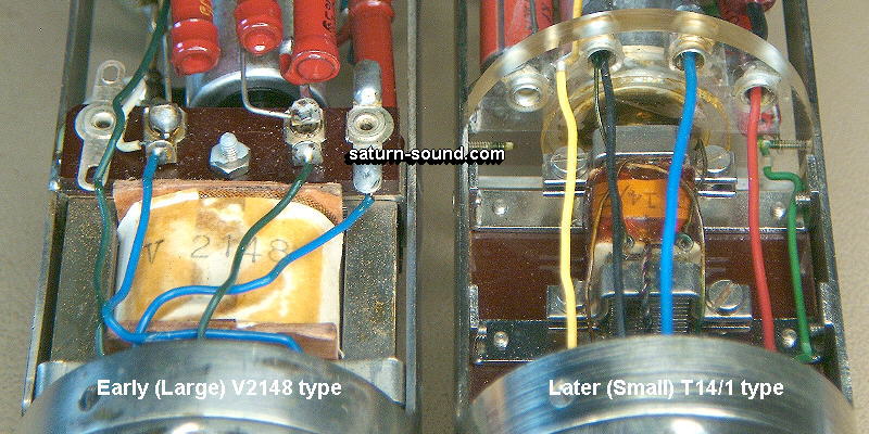
For reasons of production costs/convenience, successive models of the "Missing Link" VM-212 type microphone, use the same machined base connector as that of the VM-951 model. The output matching transformer used on the VM-212, shown in the picture, is considerably larger than that found in the later models of the AKG C12 i.e. Transformer type 14/1. However, earlier AKG C12's used a transformer of similar dimensions to the one used in the VM-212 i.e. Transformer type V2148.. |
|
| Output matching transformer and base/connector | |
|
My "Sincere Thanks" go to the following companies, for their time and attention to detail, during the manufacture of the respective components. |
|
| Norwich Plastics (Norfolk, Gt. Britain) - ABS Mouldings | |
| One Way Circuits (Norfolk, Gt. Britain) - Printed Circuit Board | |
| Sowter Transformers (Sufolk, Gt. Britain) - Matching Transformer | |
| Spray UK 2000 (Leicestershire, Gt. Britain) - Powder Paint Finish | |
| Yellow Metal Racing (Norfolk, Gt. Britain) - Base Assembly | |