![]()
![]()
![]()
![]()
![]()
![]()
![]()
----------
![]()
|
Replacement Valve - RV-14m, Design and Construction |
|
|
Requirements |
|
|
The RV-14m would need to meet the same specification, as that of the original Telefunken VF14. Modifications to the associated microphone and/or power supply are not required. The RV-14m is to be a plug-in replacement. |
|
|
The VF14 was designed for use in portable RF applications and therefore, in such situations, might well be connected quite different to that in the impedance matching circuit of a microphone. Therefore, for use in a microphone, some of the internal connections of the glass bulb (valve proper), need not be brought out on the respective pins of the valve. |
|
|
Note - For the reasons mentioned above. It is not recommended that the RV-14m is used in RF type circuits, as a replacement for the VF14. |
|
|
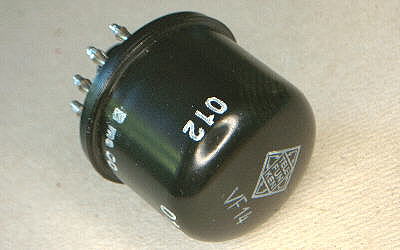
An original "Telefunken" VF14 |
|
|
In the beginning ..... |
|
|
The original idea, conceived sometime in the early 1980's, was to find a suitable valve, that would actually work in the U47 circuit. One of the problems would be, finding a device that would physically fit in the space permitted. Ideally, Subminiature types and Nuvistors, should not be used, as they get "Too Hot" in such confined spaces. This would reduce the life expectancy of the valve considerably. The use of the 13CW4 Nuvistor, in the U47/48, is a prime example of this. |
|
|
When a "Possible" valve is found, the device could then be fitted into a socket assembly that would simply fit into the original valve socket of the microphone. A few devices were tried, such as the GE407a, but with very little success. So, after very many years of frantic searching for a suitable "Substitute" device (somewhat akin to trying to find "Hen's Teeth") the idea was eventually banished to the waste bin ! |
|
|
One of the valves tried, in the VF14 type socket adaptor |
|
2005 - A Fresh start, and a better approach! |
|
|
Some 20 years had passed, since my last efforts of finding a replacement etc, for the VF14. "Good" VF14's were now scarcer than ever ..... it was time to find away around the problem fast. |
|
|
For obvious reasons, I wanted to keep the sound and electrical qualities of the Telefunken VF14. The only way to do this, would require a custom made valve being manufactured. To justify the large financial outlay of such a project, the valve would also be used in other "Missing Link" designs and modifications. Therefore, it was decided that the valve should be designed, cosmetically, around that of a smaller format type. Then being fitted into a suitable housing, with VF14 pin-out, for use in U47/U48 microphones. Of course, the physical size of the valve proper would be determined by that of the internal make-up of the original VF14. Fortunately, the final design for the custom valve, is much shorter than that of the majority of conventional low-power "Pentode" type valves. |
|
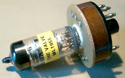
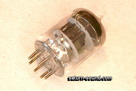
| ML-1955 during testing. Useful "B7 series" base configuration | |
|
This valve, "Missing Link" item number (ML-1955), would then be fitted into a suitable case, with VF14 pin-out configuration, to replace an "Original" VF14. Then, this new plug-in alternative to the VF14, is to be known as the "Replacement Valve"-14m. Where the suffix "m" stands for selected low noise valve, suitable for use in microphones. |
|
|
Of major importance, for long valve life and stability, is that of heat dispersion. At around 1.5 Watt's, this is quite straightforward. In the case of the RV-14m, the "Valve Proper" is fitted/coupled, both acoustically and thermally, into a suitable enclosure. This, also enables the appearance of the RV-14m, to be "In Keeping" with that of the "Original" VF14. |
|
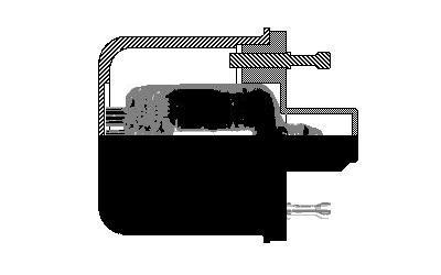
| Sectional view of the RV-14m, as drawn during the design stage, back in June 2005 | |
|
The enclosure/case of the RV-14m consists of two parts i.e. The Base, connector, and the Cap, cover. These items being manufactured from "High Temperature" ABS, which offers all of the electrical/mechanical properties required by the design. |
|
|
The connector pins of the original VF14, were designed to be a "lock-fit" to the valve socket, and suitable type pins would therefore be required for the new RV-14m. Thus enabling the same type of "Lock-fit" connection to take place. Gold plated pins are used, to improve reliability, which was a "Age Related" problem on the original VF14. |
|
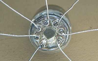
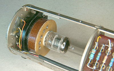
| Internal view of the RV-14m, prior to fitting the valve etc | |
Selection and Testing the Valve |
|
|
Prior to fitting the ML1955 valve into the RV-14m assembly, each valve goes through a series of "Quality Control" tests. One test being that of measuring the "Self Noise" level of the valve. Therefore making sure that the valve is suitable for further testing or rejection. |
|
|
Once the valve has passed the above test, then I can carry out a "Self Noise" listening test. During this stage, I can study the "Type of Self Noise" found, thus allowing me to determine if the valve is suitable for use in the RV-14m. |
|
|
Note - I personal feel, that a lot of a valves tonal "Character" can be determined by listening to the "Self Noise" it generates |
|
| "Modified" U48 used during ML1955 "Selection" | |
|
The "Selected" ML1955 valve is "Hard Wired" into the base assembly of the RV-14m. All terminations on the ML1955 valve are "Wire Wrapped" and then soldered for reliability. The other end of the wire wrapped leads being soldered directly into the rear face of the RV-14m "Connector Pins". |
|
|
The sub-assembly is then "Re-tested", to check for any damage that might have occurred during the wire wrapping and soldering stages of construction. |
|
|
The "Tested" sub-assembly, is then ready for use in the final construction stages of the RV-14m valve. |
|
| "Sub-assembly" of the RV-14m | |
|
After "Final Completion", each valve is given a "Vibration" test. Short of the valve being "Crushed", this test "Emulates" any problems that could occur during delivery/shipping. The valve then goes through the same series of "Quality Control" tests as that during "Selection" of the ML1955, thus ensuring that each valve is still working to the required specification. |
|
|
The "Fully Tested" valve is then given a "Serial Number", wrapped in bubble-wrap, and placed in it's cardboard box ready for use. |
|
|
Note - All of the above "Production Tests", are carried out using a modified U48 microphone. The capsule is removed and a "Dummy" load is used in it's place. The original valve holder is replaced with a "Chassis" mounted version, thus giving more space and extra strength, during the many tests required. The rest of the microphone and PSU is "Original". |
|
|
A "Socket Adaptor" is used, to allow the testing of the smaller ML1955 valve in the larger valve socket during the Selection tests. |
|
| "Final Testing" of each completed RV-14m valve | |
|
My "Sincere Thanks" go to the following company, for their time and attention to detail, during the manufacture of the respective components. |
|
| Cardage Ltd (Leicestershire, Gt. Britain) - Screen Printing | |
| Norwich Plastics (Norfolk, Gt. Britain) - ABS Mouldings | |

